Building a smart fan controller with Raspberry Pi
Final PCB Assembly and Testing
I've now combined all the circuits we designed onto a single PCB in KiCad. I also rendered most of the components in 3D to visualize the layout. The board is organized with power handling on the right, I/O interfaces on the left, and fan/power control at the bottom.
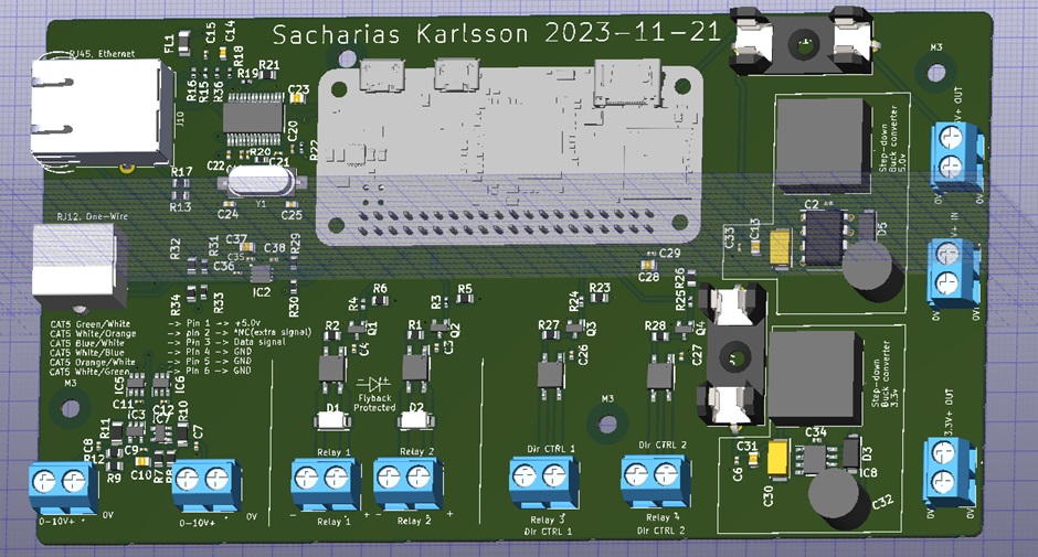
The Raspberry Pi is mounted in the center, using the GPIO header rows, essentially serving as a "hat" for the PCB. I chose the Raspberry Pi Zero since it doesn't require much processing power, and the Pi is securely held in place by the pin header—no screws needed. Although I used the Pi Zero, this design should be compatible with any Raspberry Pi that has a GPIO interface.
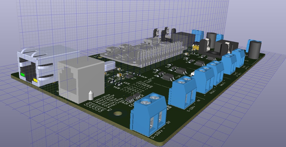
For a bit of fun, I added some custom artwork behind the Raspberry Pi as a hidden easter egg on the silkscreen layer.
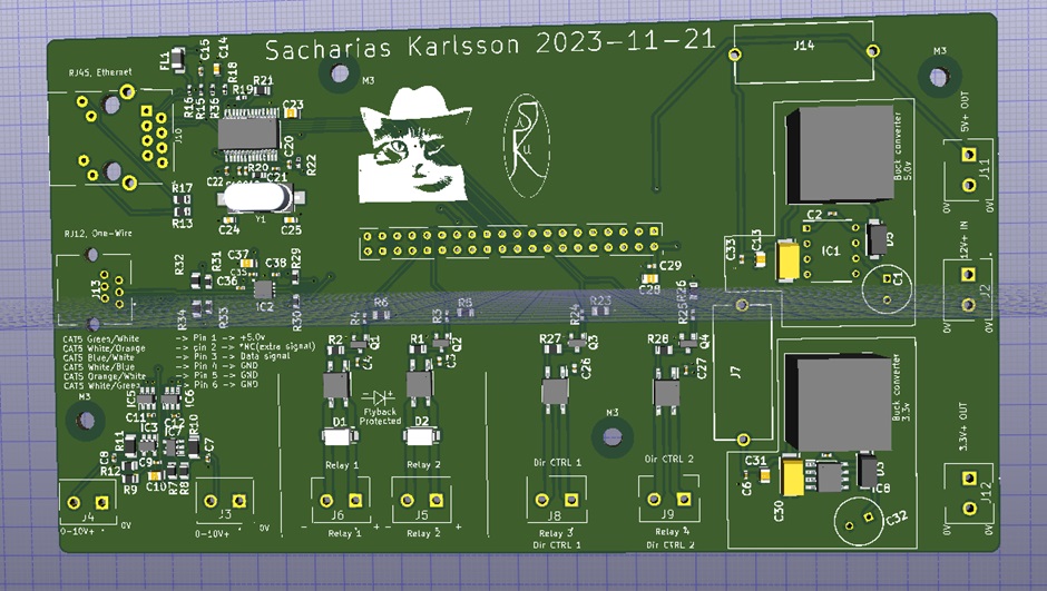
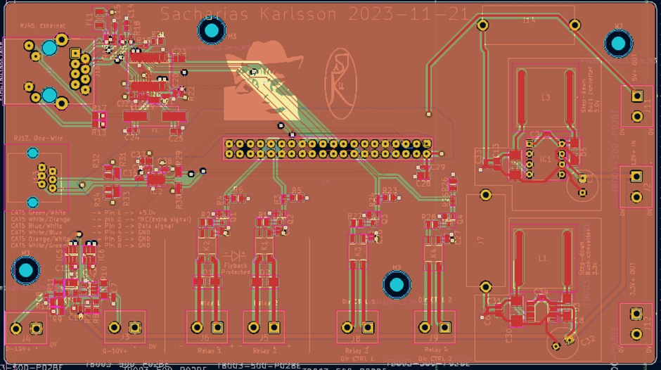
And the different layers of the PCB:
Component assembly
Once the design was complete, I ordered the PCB from AISLER. While their prices are higher than some manufacturers, I prefer having the production done in Europe instead of China. The PCB arrived promptly, and I populated it with components sourced from DigiKey and Mouser. I ordered enough parts for two boards, so I'd have a spare in case anything went wrong—one for experimentation, and one for use.
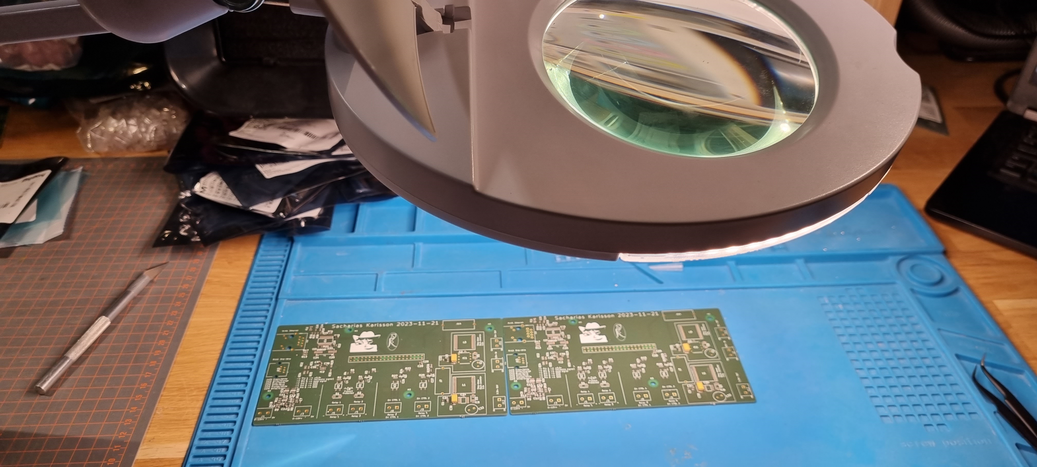
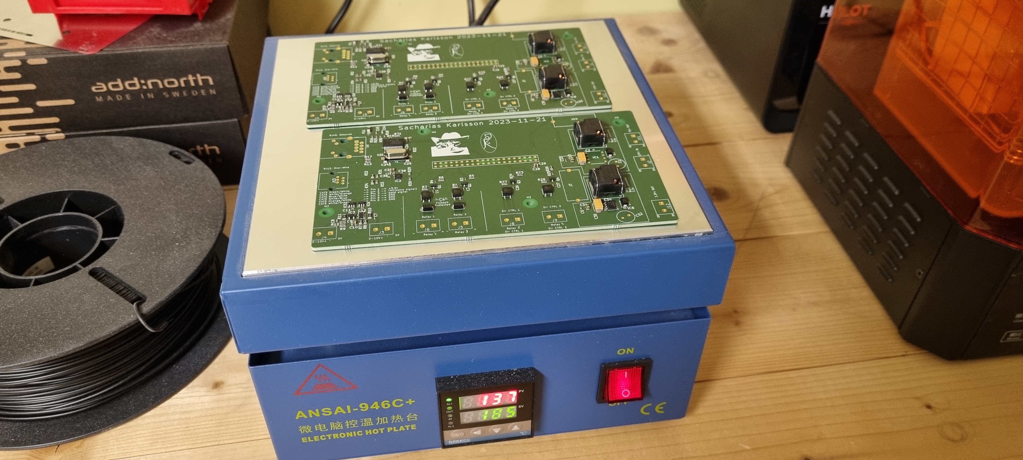
I started by placing the surface-mount components and cooking them on a hotplate. This was my first time using low-temperature solder paste, and it worked well—much better than regular paste, which I've previously used to only end up accidentally charring the PCB I have been working on. While it may not be as strong as standard paste, it does the job for this application.
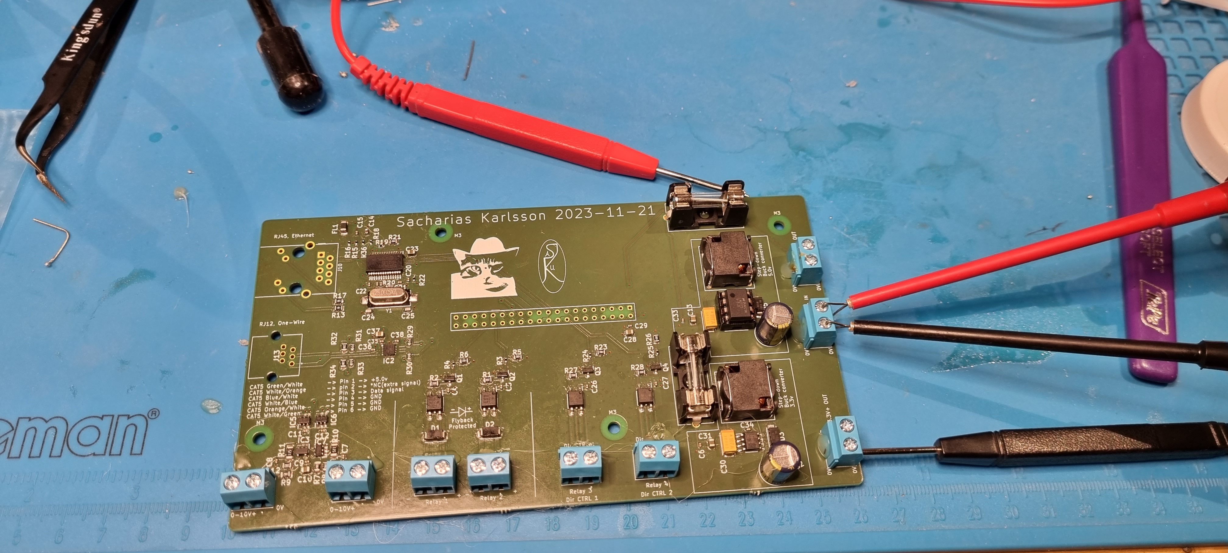
Next, I tested the buck converters to ensure they were working before adding the Raspberry Pi. This way, I could verify the power supplies without risking damage to the expensive and fragile Pi.
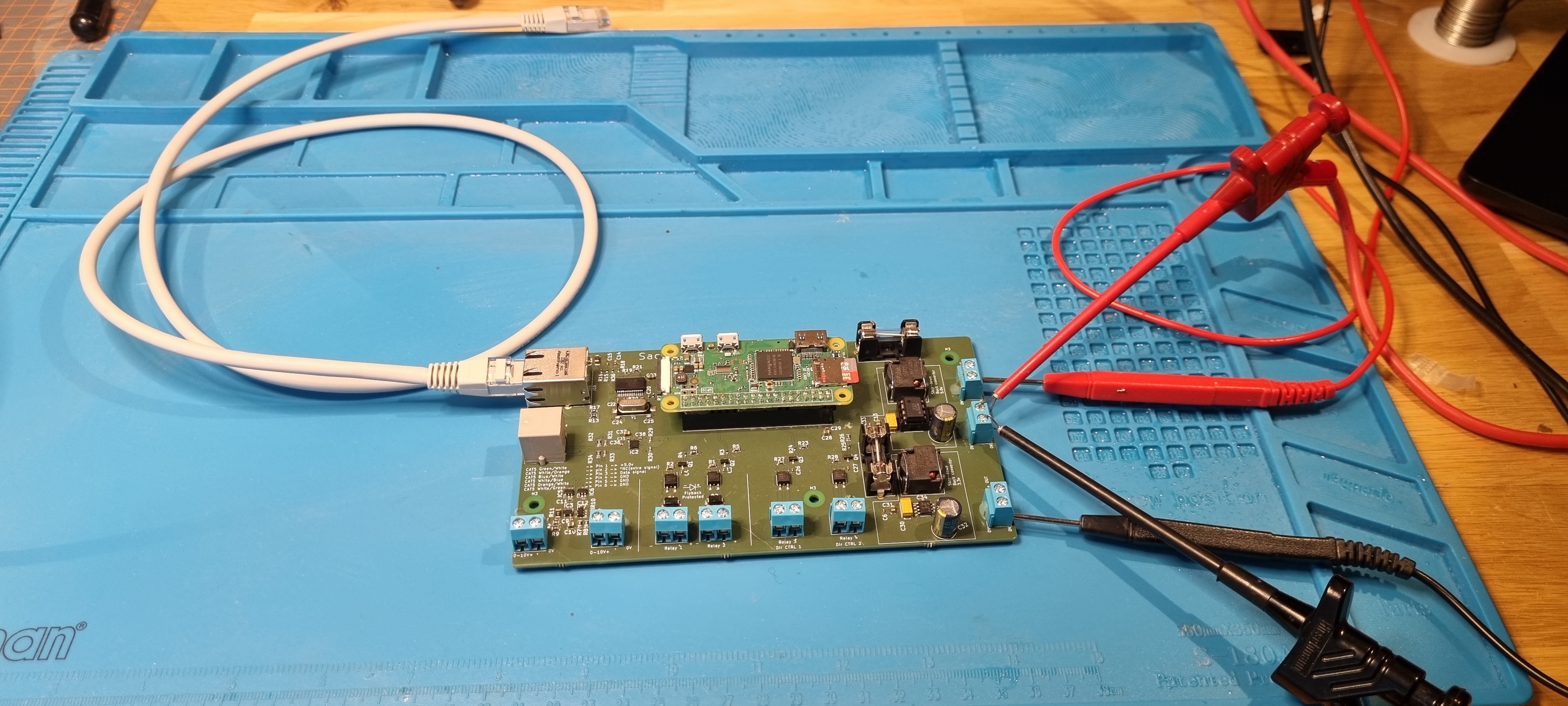
Once I confirmed the converters were working, I mounted the Raspberry Pi on the topside of my PCB, but connected the GPIO pin header to the bottom of the Raspberry Pi (rather than the usual top side of the raspberry). I also added a female-pin header to my PCB's top for easy removal and future upgrades, allowing me to swap out Raspberry Pis without reworking my entire board. This design flexibility means I can reuse the more expensive Pis and keep things adaptable.
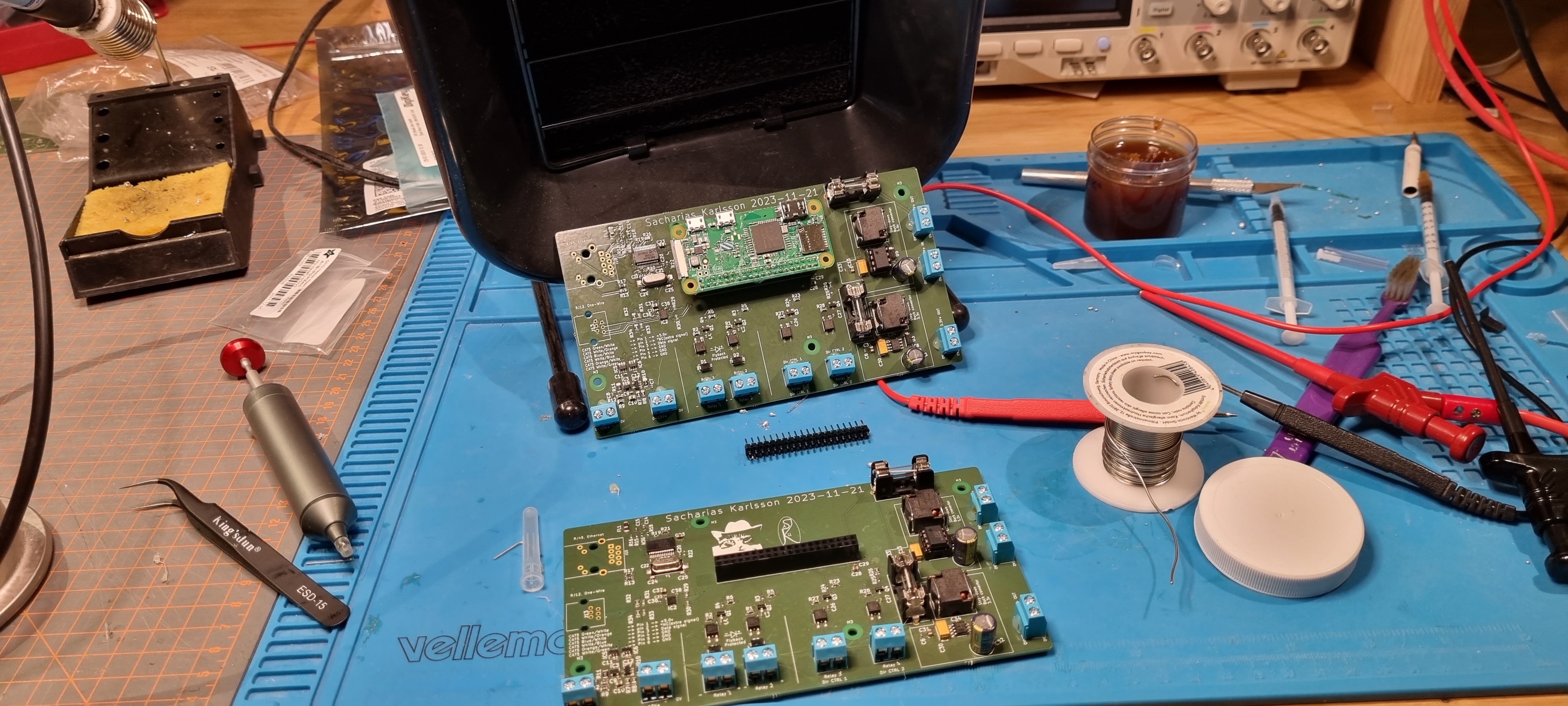
Finally, I connected the Ethernet and RJ12 jack, completing the assembly.
Final thoughts
I'm really pleased with the final result. Initial testing has been successful: I can SSH into the board, read One-Wire sensors, use the Ethernet interface, control my DAC's over I2C, and control the optocouplers via GPIO pins. Everything is functioning as expected!
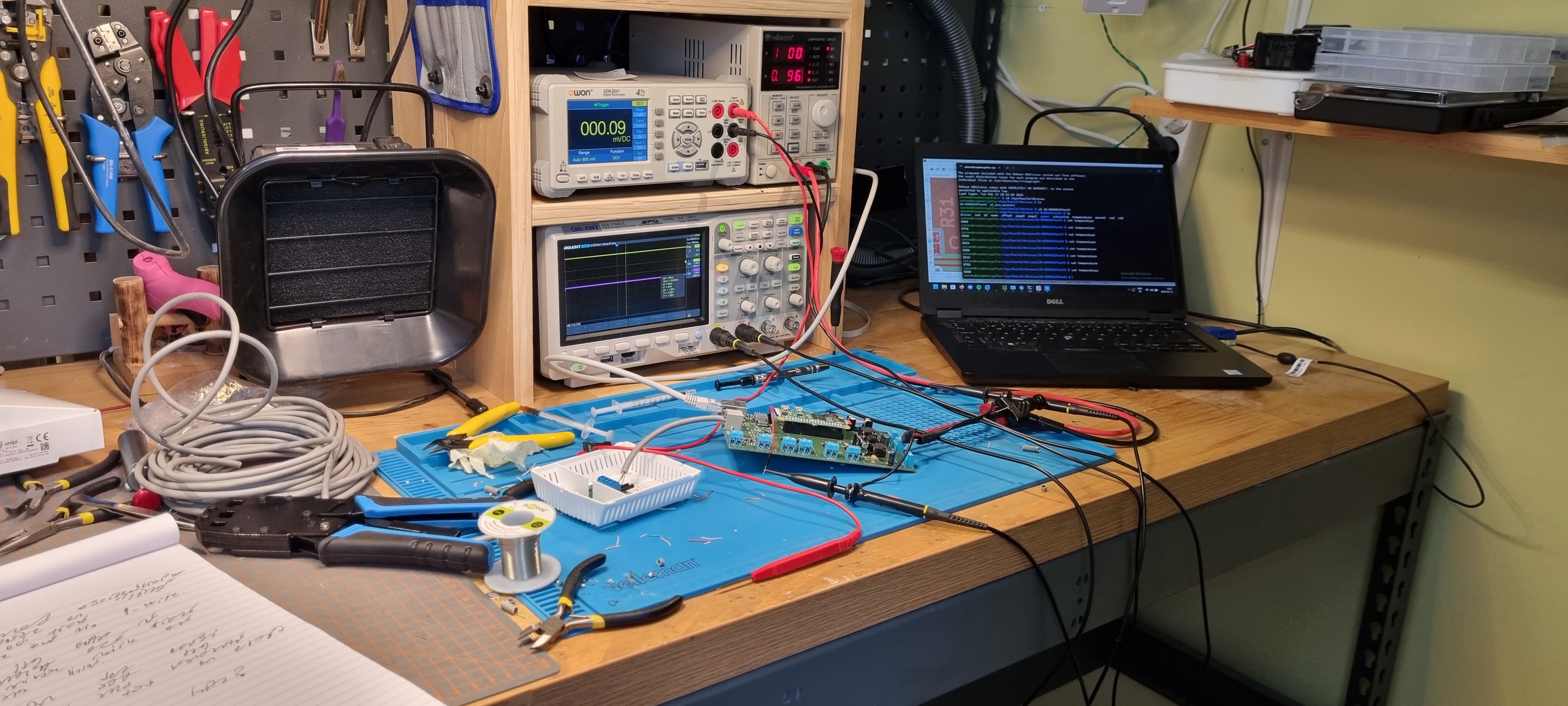
The next step is to integrate this setup into a real-world application, which I have planned for a future project.