Building a smart fan controller with Raspberry Pi
Building the Relay and SSR Control Circuit for Fan Direction and Speed
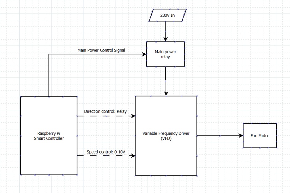
Now that we know the interface to interact with our VFD (2 relays and a 0-10V signal), it's time to implement the control system. We'll start with the relay control.
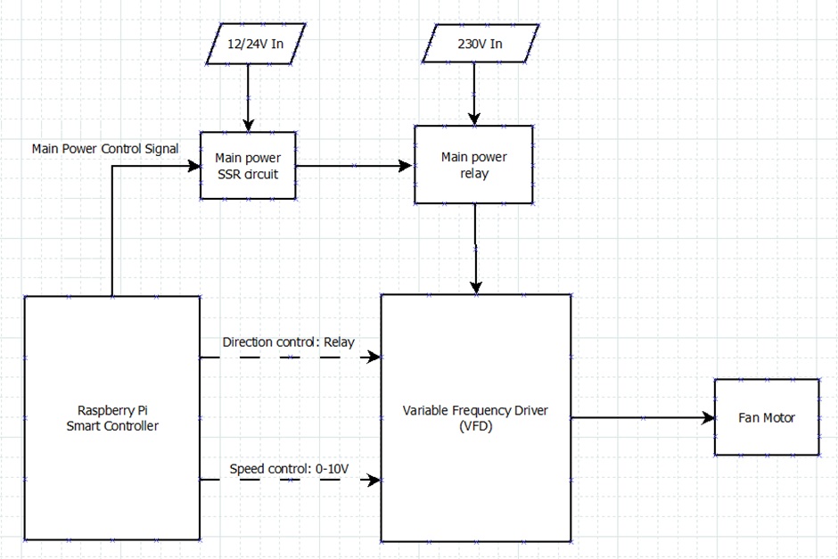
In the diagram above, we have two relays: one for the main power to the VFD and one for the direction control. We can simplify this by using the same circuit for both relays and duplicating it as needed, with minimal changes between the two to keep it simple.
I decided on using optocoupler solid solid-state relays (SSR's) for the task of the relays in our circuit, they are efficent, small and quite easy to drive, they also allow our circuit the benefits of optical isolation, which is quite nice if you are gonna switch voltages that are large and or very noisy. Small optocouplers can not typically directly handle mains level voltages, for example 230V, but you can easily control a larger inductive relay from them if you need to.
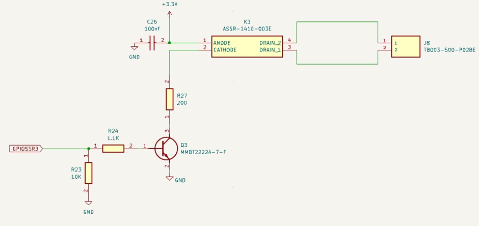
In the following diagram I drew up the circuit for one optocoupler solid-state relay(I used the ASSR-1410 optocoupler) controlled by a GPIO from the Raspberry Pi. Since the Pi can supply around 4mA from its GPIO pins, we use an additional transistor to handle the SSR, which can draw up to 20mA—too much for the Pi.
For the transistor, I selected the “MMBT2222A-7-F” which works well for driving the SSR. Let's review its electrical characteristics from the datasheet:
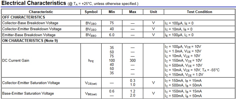
The base-emitter saturation voltage ranges from 0.6V to 2V, but with the 3.3V from the Pi, we're comfortably beyond the minimum.
Now we need to limit our current into the base of the transistor. The transistor we're using has a HFE (DC current gain) of 75 at 10mA and a minimum HFE of 100 (ranging up to 300) at 150mA. Since we'll likely be somewhere between 10mA and 150mA, but likely closer to the lower end, we will assume an HFE of 100 to keep the math simple.
Firstly, we calculate the base-emitter voltage drop (I assumed a Vbe of 0.7 as its pretty close to the minimum Vbe of the transistor but not necessarily the minimum), next I arbitrarily chose a resistor of 1100Ω as its pretty standard and should get us into the right range for base current with a HFE of 100, lets calculate with those assumptions:
Given the HFE of the transistor, we can calculate the collector current that the transistor will switch. Since the HFE represents the current gain, the transistor will amplify the base current by this factor.
This is plenty of current for our application, and it shows that the transistor will be able to easily drive the SSR(optocoupler) which will control the relay. In fact it is a bit too much and we now in turn need to limit the current to the SSR's optocoupler diode. According to its datasheet:
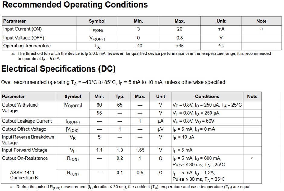
The internal diode has a typical forward voltage of 1.3V, and it operates between 3mA and 20mA. For reliable operation, we'll aim for 10mA. Using Ohm's law:
So, a 200Ω resistor limits the current through the SSR diode to 10mA, keeping the SSR well within its operational range.
Now, considering the voltage drop across the transistor (0.3V), which in turn also reduces the current through the optocoupler. The total voltage drop across the circuit is not actually 1.3v but 0.3v higher meaning 1.6V, leaving us with:
Current through the SSR diode:
While the SSR can switch loads up to 60V at 1A, we can't switch the 230V mains power needed for our VFD controller directly through the SSR; Instead, we'll use the SSR circuit to control a larger 12/24V inductive relay, which will then handle the larger 230V load for controlling the VFD. This approach allows us to keep mostly the same circuit for controlling smaller loads directly with the SSR but the flexibility to add a large relay at the end of the circuit if need be for larger loads.
However, when driving inductive loads like traditional relay coils(such as the case where we use the same circuit to drive a larger relay for VFD power), we must account for the back EMF (electromotive force) generated by the inductor. To suppress this back EMF, we add a flyback diode across the output leads of the SSR. In this case, in the diagram below, D1 represents the flyback diode. With this addition, the SSR can handle reverse polarity events, such as the induced reverse voltage from the back EMF (flyback) of a inductive relay turning off. While the SSR's output is designed to manage reverse voltage events, the flyback voltage could be significantly higher than the input. The D1 diode is primarily there to clamp the flyback voltage, ensuring it stays within safe limits for the SSR output, rather than serving as a standard reverse voltage protection.
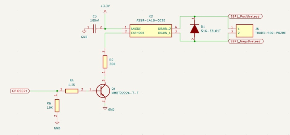
This ensures that our SSR circuit can safely handle reverse voltage spikes. The final setup will look something like this (NOTE: direction is still simplified even though the direction control uses the same SSR control circuit as the Main Power SSR circuit):
