Building a smart fan controller with Raspberry Pi
Powering the Controller Board: Designing 3.3V and 5V Supplies
We've now outlined the full controller board, including the 0-10V speed control, relay driver for fan power and direction, and Ethernet controller—all connected to a Raspberry Pi. The last step is powering everything.
So far, we're working with three voltage levels in our circuit: 3.3V, 5V, and 12V—pretty standard. Instead of inputting three different voltages, it's more efficient to use one voltage and step it up or down to the others. The easiest and most efficient way to do this is by stepping down voltage, and since our highest voltage is 12V, we'll convert it to both 5V and 3.3V to power the entire circuit from a single 12V source.
We'll need two step-down (buck) converters to convert 12V to 5V and 3.3V. After some research, I found the LM2675 switching voltage regulator, which has variants for 12V, 5V, and 3.3V outputs, with a wide input range of 8-40V, perfect for our needs.
The LM2675 datasheet is one of the best I've seen. It makes circuit design easy, listing required auxiliary components, suppliers, and alternatives for different output voltages, very plainly and easily understood.
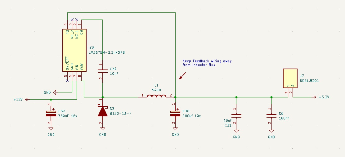
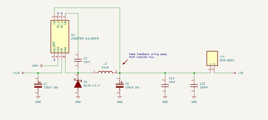
I used the datasheet to design both the 3.3V and 5V circuits, aiming to minimize component differences. The only distinction between the two circuits is the IC controlling the output, helping simplify the design.
Here are the resulting circuits for 3.3V and 5.0V:
3.3V circuit:

5.0 circuit:

I specified them to be specified to be able to be loaded to around 700-900mA for the 5.0v circuit and 500-600mA for the 3.3v circuit, I doubt I will be drawing that much current from either circuit but it feels good to be able to deliver quite a lot of current to my circuits. I also added the fuse holder J7 and J14 to each of the circuits output.