Turning a CRT TV into an audio-visual oscilloscope
Interference Troubleshooting and Final Build
What I needed next was an audio amplifier. Without one, I'd have to input a ridiculously strong audio signal from the outside, which would make it impossible to connect the CRT to a regular audio source like a computer or phone without amplifying the signal first. So, I needed to fit an audio amp inside the TV.
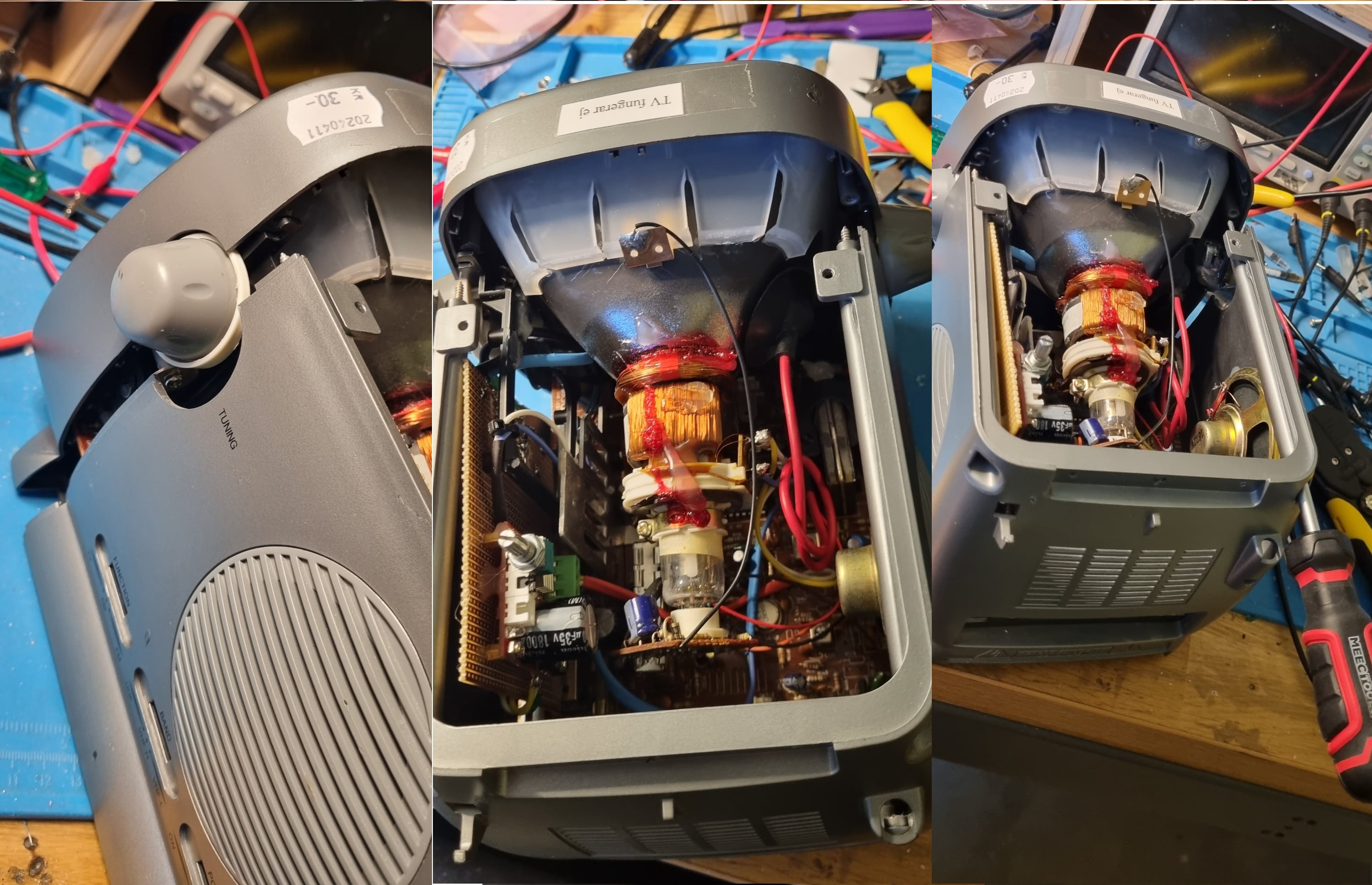
Luckily, we already removed the radio board earlier, which left us with plenty of space inside to house the amplifier! Everything seemed to be falling into place. I picked up a cheap audio amp from Amazon, and it fit perfectly in the spot where the radio board used to sit.
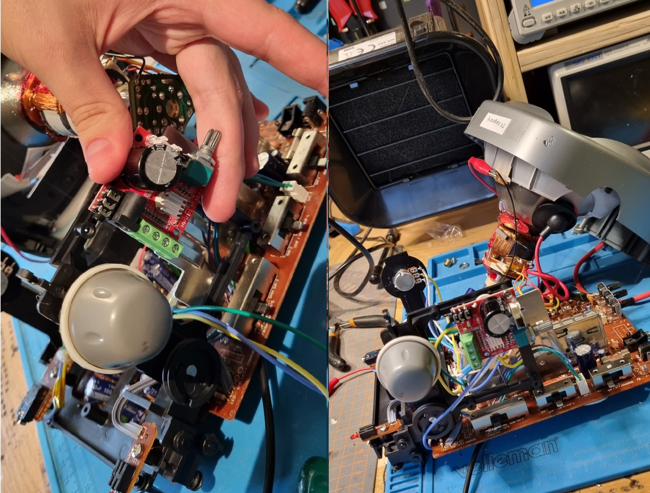
At this point, I hooked up the audio signals to the potentiometers on either side of the CRT and routed the output to the audio amp, which I mounted on the top right
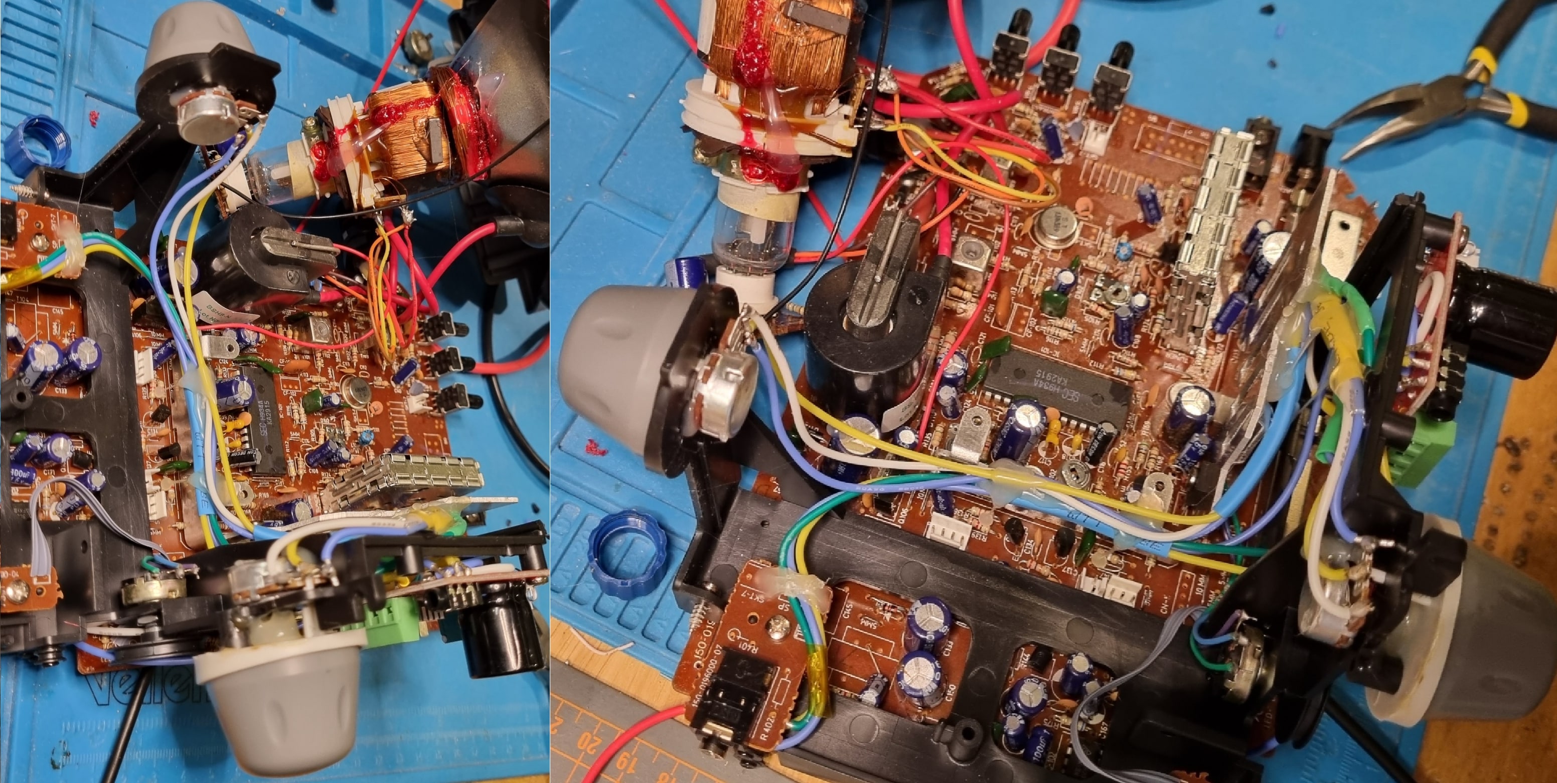
The audio board's output was then connected directly to the deflection coils of the CRT. But, if you look closely at the setup, you might notice an issue: the audio cables are running right next to the flyback transformer, with no shielding between them. This means they're going to pick up a ton of interference—something I'd soon regret ignoring.
Sure enough, when I powered it up, the left audio line (which is closest to the transformer) was hit with massive interference, making the waveform super noisy. In the image below, where the CRT should be drawing a circle, you can see how the left signal (yellow trace on the oscilloscope) is all messed up compared to the right one (purple trace).
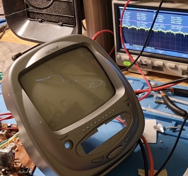
The interference got so bad that it even crashed my audio amp multiple times, sending it into an unrecoverable state where it stopped amplifying the audio signal altogether. I spent ages troubleshooting this, thinking the amp itself was faulty when, in fact, it was all down to that flyback noise.
To try and fix it, I spent a lot of time making RC filters for the audio lines, tweaking different values to try to clean up the signal. This helped a bit but didn't entirely solve the problem. In the end, I realized the issue wasn't just the filtering—it was the unshielded cable carrying the audio signal.
So, I swapped out the old cable for a dedicated audio cable with built-in shielding to protect it from the interference. And that finally did the trick! The noise was gone, though it took way more work than I'd expected, simply because I hadn't thought about interference earlier.
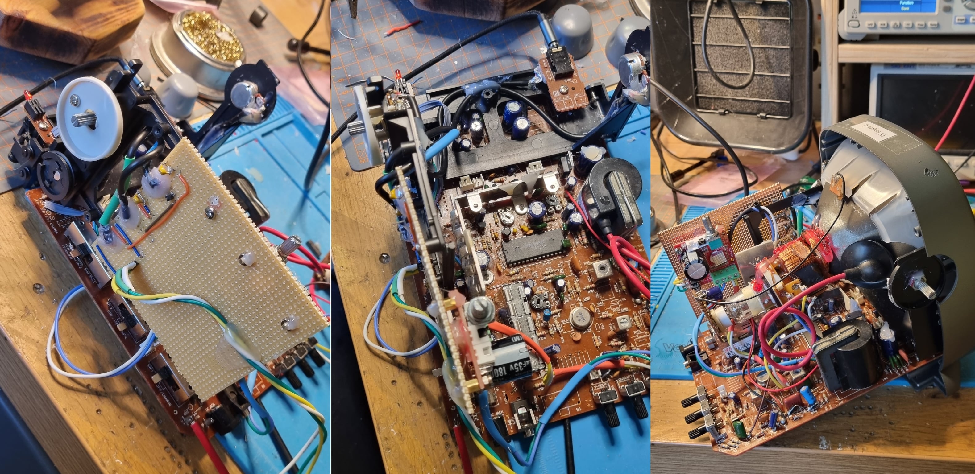
I mounted the filters and audio amp on a spare proto-board I had lying around, screwing it in where the radio board used to be. At this point, I finally had a functional setup that could draw oscilloscope art using audio signals, just like I had planned from the start.
It was a pretty tight fit, but I managed to cram the new board and all the cables into the original enclosure with a bit of "light percussive persuasion." The best part is, I kept everything inside the original case, so from the outside, you can't even tell it's been modified. I guess you could call this a “sleeper build”?
In the end, I managed to create a working oscilloscope that lets me draw XY oscilloscope art, which was the whole goal of this project. While it might not handle the highest frequency art perfectly, it works!
One of the main things I wanted to do with this project was draw a mushroom, which is pretty popular in the world of XY oscilloscope art. And I'm happy to say I succeeded! It might not be the most detailed or polished mushroom, but it's my mushroom, drawn from a piece of non-functional junk that I bought for 30kr!