Turning a CRT TV into an audio-visual oscilloscope
Audio Signal Input hack
At this point, I've got horizontal and vertical deflection attenuation control, and I know which coil controls which direction. Now, the next step is to get a signal into the TV that can manipulate those deflection coils. Usually, when modifying CRTs like this, people use an audio signal because it lets you visualize sound waves. I'm thinking I'll do the same.
The great thing about focusing on audio signals is that you're dealing with a much smaller part of the frequency spectrum and voltage range. This makes designing circuits way easier. Plus, you can use audio mixers and amplifiers to control the signal, which is nice because it's a much cheaper market compared to the more specialized (and expensive) electronics you'd need for higher frequencies and voltages.
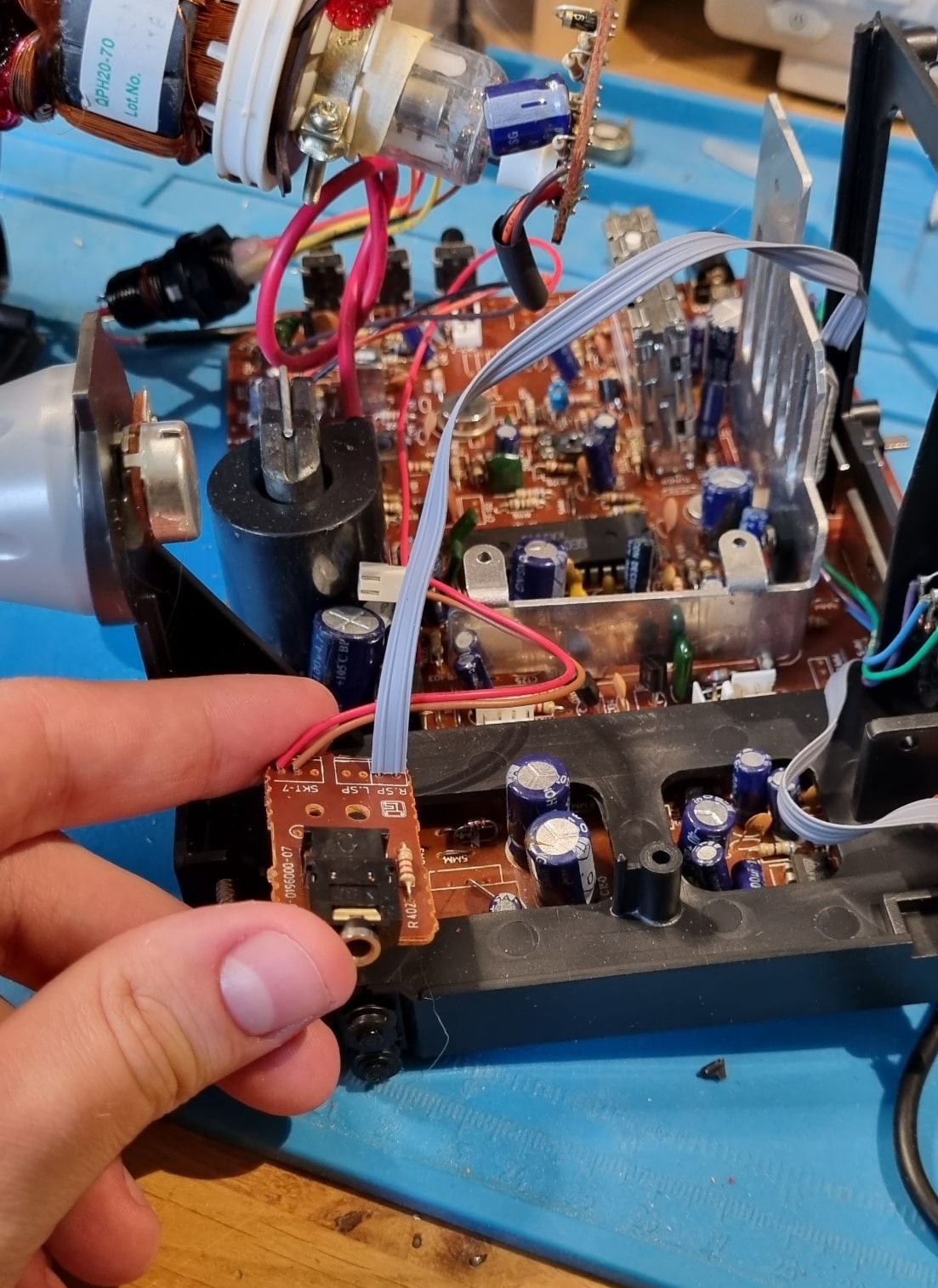
What makes this even better is the TV/radio feature of the CRT. It actually has an audio jack out so you can plug in headphones to listen to the radio or TV. Since I don't need that audio jack out (we're definitely not listening to any radio on this thing, especially since I've already removed the radio board), I can repurpose it. I'll modify it to act as an audio jack in for my input signal to control the CRT.

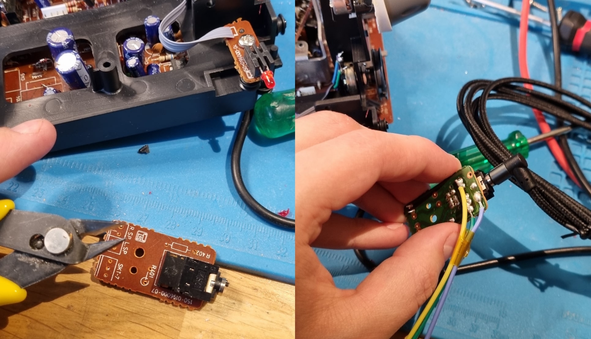
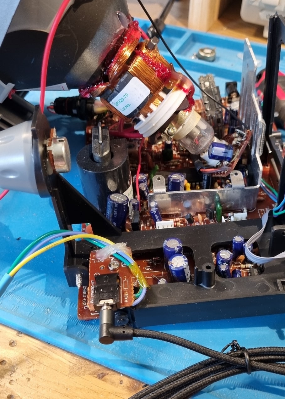
With a few small modifications, I can make this work. I started by cutting away some of the small components on the board, including a few resistors that were in series with the audio lines. Not sure why they were there, but I didn't need them, so they're gone. I also scratched away some traces that connected the audio lines together, making sure the signal was properly isolated. Then, I soldered new cables for the audio input, so now the original jack will serve as a way to feed signals into the CRT.
What I like about this setup is that I'm able to keep the outward look of the CRT pretty much the same. I want it to look original and not super hacked-together from the outside, even though the inside is definitely a bit of a hack job!

So now, I've got a neat way to connect the audio signal using the original audio port. I think it's a pretty clever solution! The best part? I could screw everything back into place, and it fits perfectly. No damage, nothing ruined—it still looks like the original setup!
