Turning a CRT TV into an audio-visual oscilloscope
Modifying the Controls for Oscilloscope Use
Originally, the knobs on the left and right sides of the CRT were used for adjusting brightness and volume. But since I wanted to turn this into a makeshift oscilloscope, I had a different use for them in mind. I thought I could repurpose the left knob for controlling the horizontal voltage scaling of the deflection coils and the right one for the vertical scaling. This way, I could adjust or "attenuate" the vertical or horizontal lines, which could be super handy for an oscilloscope-type setup.
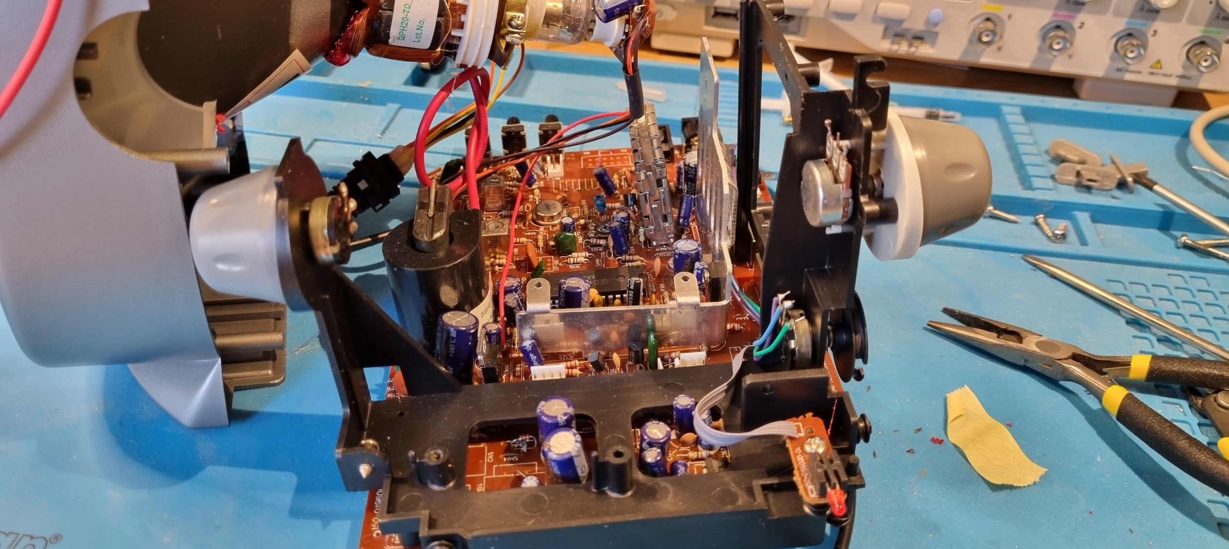
To make this work, I planned to run the input voltages through a potentiometer on each side, allowing me to adjust the voltage going to the deflection coils. However, when I tested the original potentiometers, I found they had dead spots and inconsistent resistance. This meant I had to replace them with new ones, but I still wanted to reuse the actual original knobs for that vintage look.
The first step was to remove the old potentiometers, and that turned out to be a real pain. They were glued in tightly and wouldn't budge, even after I tried everything from heat to isopropanol and acetone. I eventually had to destroy the old potentiometers just to get them out. Instead of removing them through the front of the knob like I hoped, I had to pull them apart from the backside.
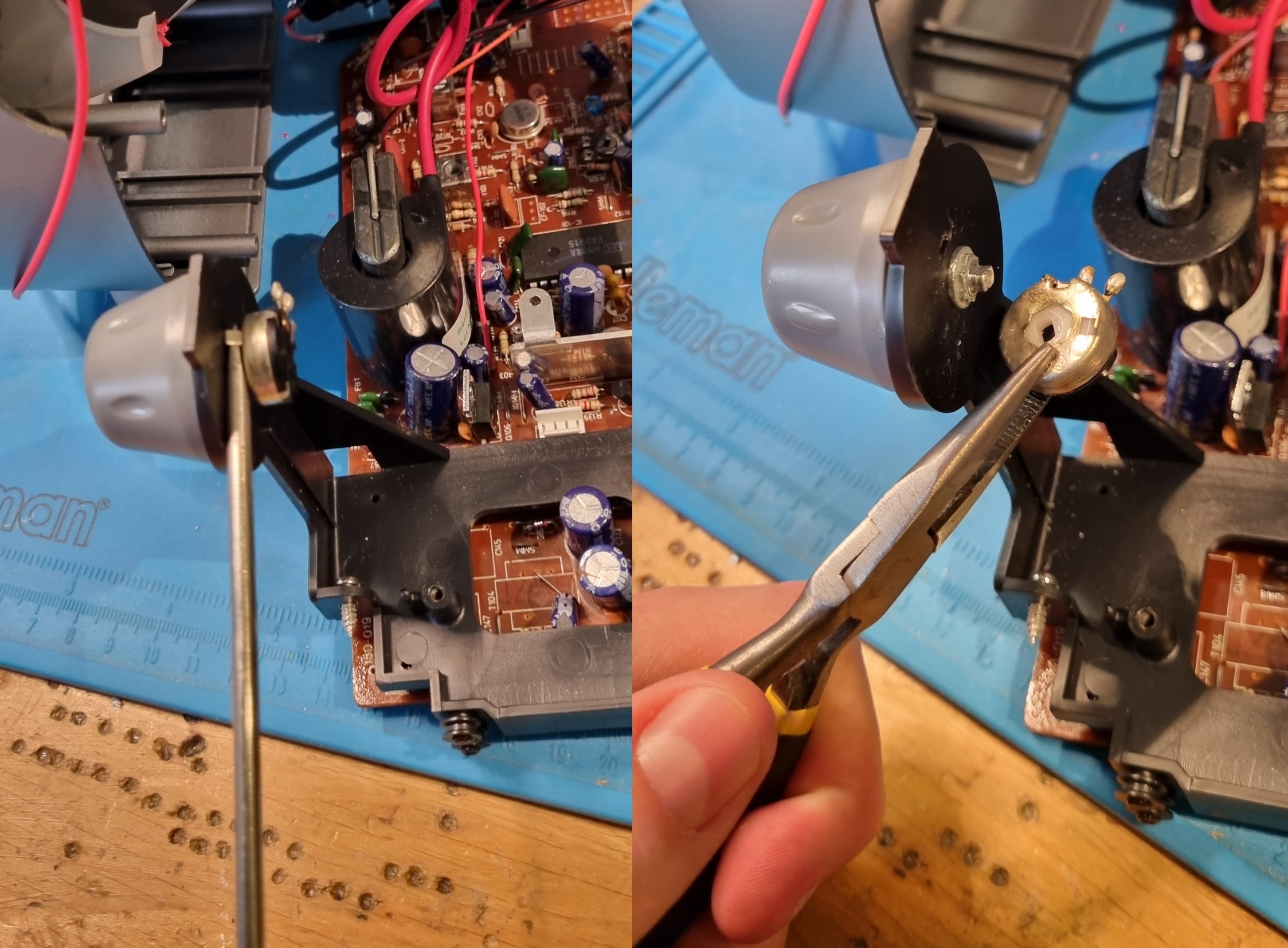
After ripping off the back of the potentiometer, I was finally able to push the shaft out from behind. Not the cleanest solution, but it worked! Once the old potentiometers were out of the way, fitting the new ones in was relatively straightforward.
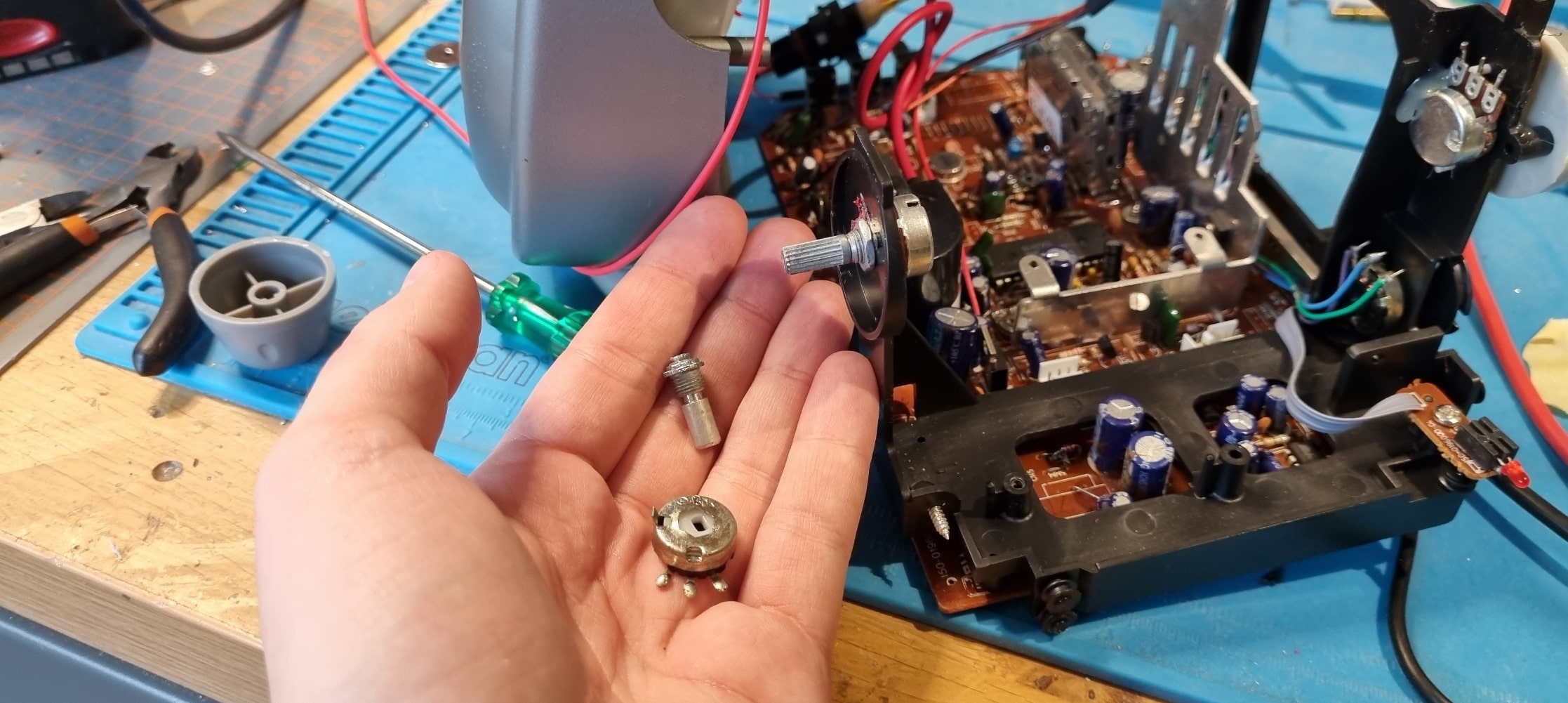
Next, I had to make sure the original knobs would fit the new potentiometers. The holes in the old knobs were a bit too small for the new shafts, so I had to carefully drill them out. This was a bit nerve-wracking because I really didn't want to damage the knobs. sure, I could 3D print replacements if I had to, but that wouldn't have the same feel as the originals.
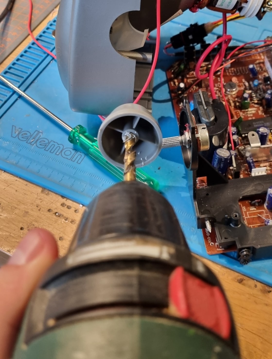
Luckily, the drilling worked out perfectly, and I was able to fit the old knobs onto the new potentiometers without any issues. It felt like a small victory to keep that classic look while upgrading the internals!
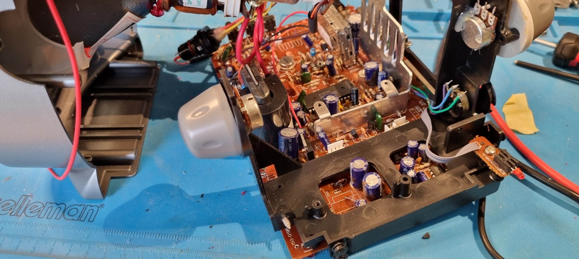
Instead of using an adhesive as strong as the original, I went with hot glue. This way, if I need to service or replace the potentiometers in the future, I can do so without causing any damage or destroying the knobs.