Restoration of an old Oltronix power supply
Turning it on
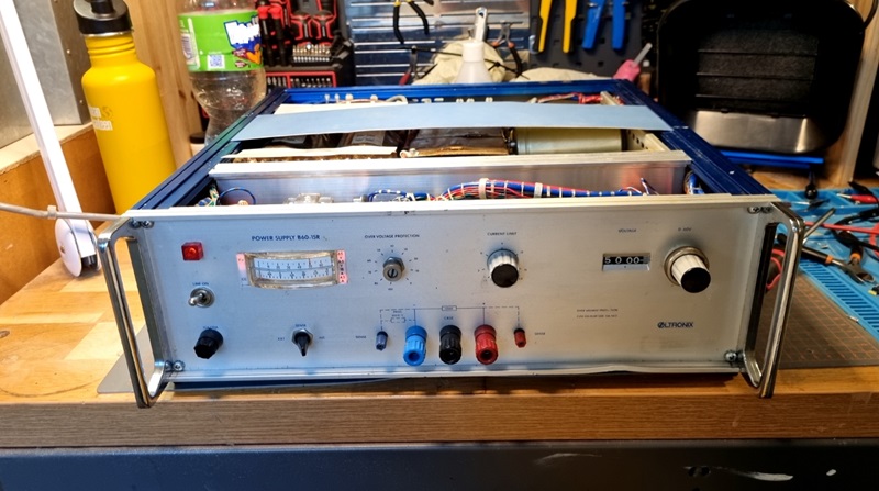
I continued reassembling everything and flipped the main switch, and to my delight, it powered on immediately! After some initial testing—turning the knob and setting the sensing switch to internal—I cross-checked the output with my bench-voltmeter. It was off by about 200mV across most of the 0-60V range (though a few spots were further off). Still, for such an old, inexpensive find, it was more than usable! While this was done with no load, it showed a lot of promise.

However, during my next round of testing, things took a turn. I powered it off and back on, and... it tripped the breaker. Oops. I gave the supply a quick visual inspection, hoping to spot any obvious damage, like burn marks or charred components, but nothing stood out. I reset the breaker and tried again—same result. It seemed the power supply would need more attention to get it fully operational.
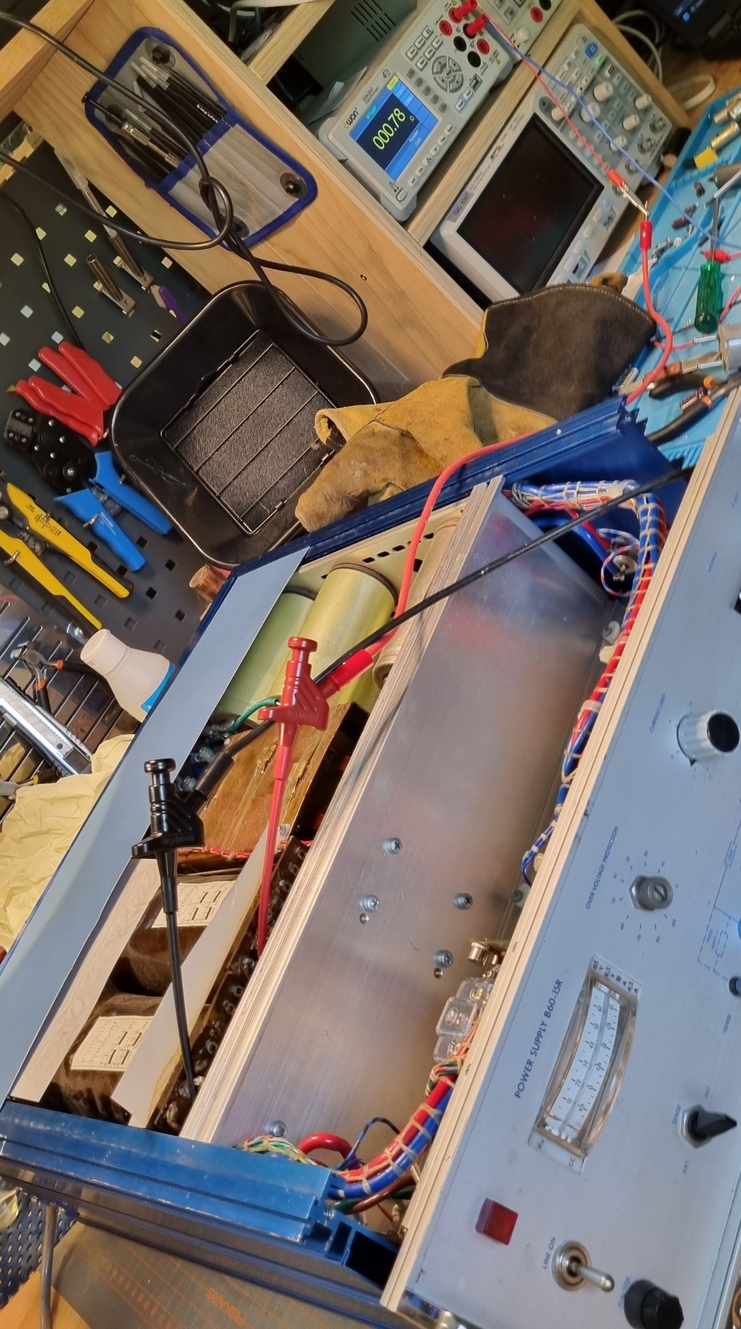
Feeling a bit discouraged, I took the supply apart for a deeper inspection, cleaning up any areas that were dusty, oily, or dirty. Again, nothing stood out as obviously wrong. Testing the main transformer's primary leads, I measured 0.78 ohms. That seemed a bit low, but given the size of the transformer, I figured it was just the winding resistance, which would likely increase under load.

Moving on to the primary board, I began testing components by desoldering one leg at a time. A few capacitors were way out of spec, so I temporarily swapped them for newer ones. Most of the diodes tested fine, showing a voltage drop of around 0.5V. Despite my efforts, nothing definitive turned up. I did notice a deep scratch on the main board's copper plane, which could potentially cause issues, but I wasn't convinced. I bridged the scratch with solder just in case—it almost looked as if someone had scored the board intentionally.
After all that, I reassembled everything. Realizing that using a 10A breaker might be contributing to the issue, I decided to switch to a 16A breaker instead. I plugged it in, powered it up, and—success! The supply started up without tripping the breaker or blowing the fuse. A small victory!
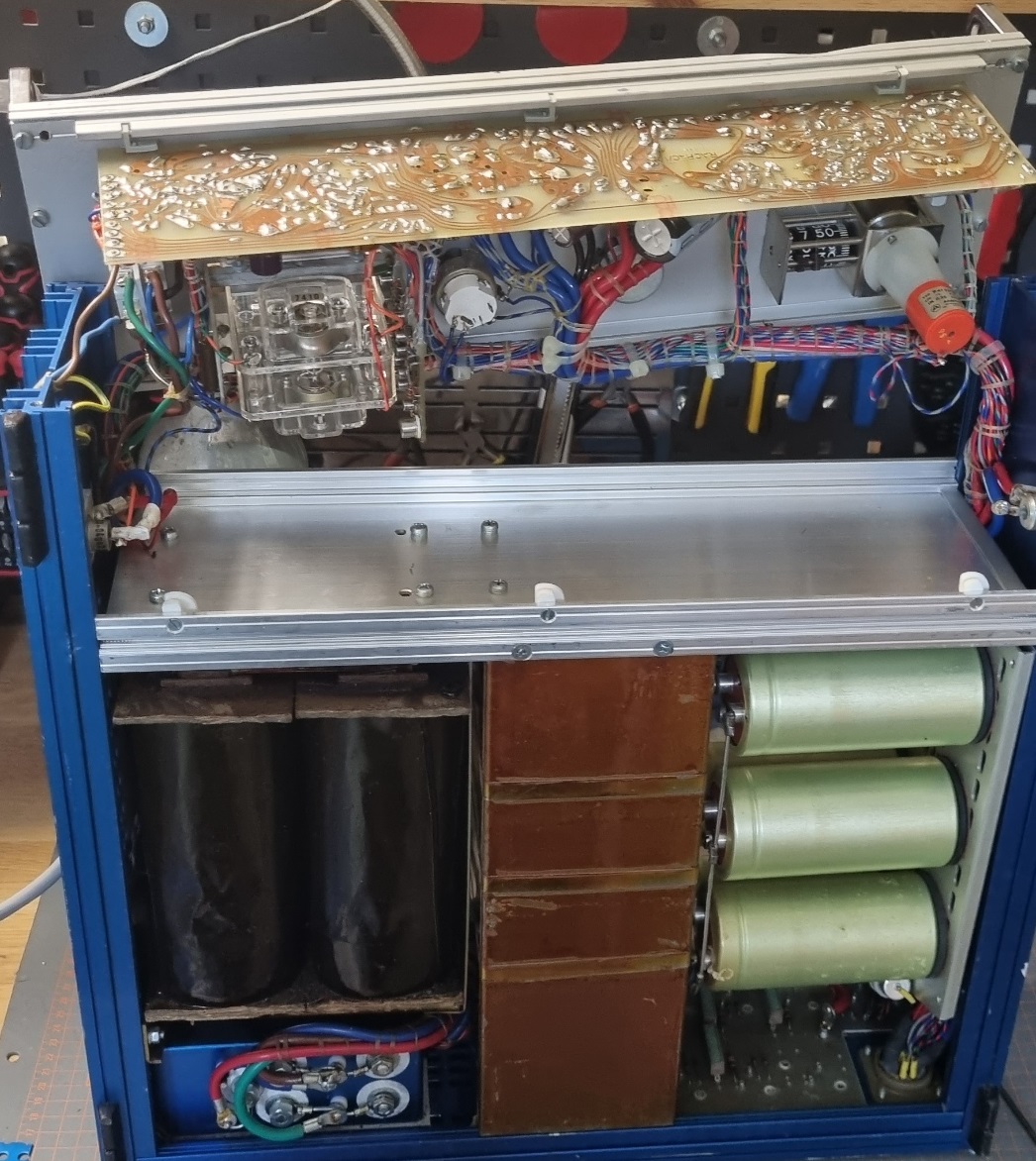
 In the picture above, you can see one of the two rows of the massive capacitor bank located in the bottom right corner.
[1]
An unexpected piece
2024-06-25 |
[2]
A first look
2024-06-26 |
[3]
Turning it on
2024-06-27 |
[4]
The Manual
2024-06-28 |
[5]
Leaky discovery
2024-07-06 |